Showing posts with label FOG loading. Show all posts

Thursday, March 5, 2015

YouTube Video - Grease Production Sizing Method

I realize that I recently blogged about the topic of Schier's Grease Production Sizing Method (here), but as I travel around the country visiting with pretreatment professionals I repeatedly see the need for a better sizing approach for grease interceptors.

http://youtu.be/c3HLV3dF89cSchier created a video to provide another tool to help jurisdictions, specifiers and contractors to not only understand how to size by grease production but also to be able to quickly explain the method to anyone else.

Flow rate or liquid volume based sizing for grease interceptors is inaccurate and inadequate, having led to thousands and thousands of incorrect installations across North America.

Grease Production Sizing is the only method that considers how much grease a restaurant will produce to ensure that the grease interceptor selected has enough capacity for a consistent and affordable pumpout schedule.

Here is a link to the video if you want to check it out:

http://youtu.be/c3HLV3dF89c

Monday, February 2, 2015

The 25% Rule; where did it come from?

Have you heard of the 25% rule?

In case you are unaware or have been off-planet for a while let me explain.

The 25% rule is used primarily by pretreatment authorities to determine when a grease interceptor (or oil separator) is full. A fairly universal definition would be:

"The total depth of the floating grease layer plus the settle-able solids layer cannot exceed 25% of the total liquid depth of the interceptor."

Determination is made by taking a core sample with something like a Sludge Judge or Dipstick Pro (I know of a few jurisdictions that use florescent light covers (clear plastic tubes) from Home Depot or Lowe's, with a rubber stopper).  The device is lowered slowly through the fats, oils and grease layer all the way to the bottom through the solids layer of the interceptor and then capped or plugged and slowly removed and set aside to rest.  This allows the captured FOG to collect at the top of the device while the solids settle at the bottom.

A measurement is taken, typically in inches, from the top of the FOG layer to the bottom of the device, which represents the tanks total water column.  Then the FOG and solids layers are each measured, also typically in inches, and added together.  If the combined FOG and solids layers are equal to or greater than 25% of the total water column then the interceptor is considered full.

For example lets take a typical gravity interceptor in the field like the one pictured here on the left. 

The technician is using a Dipstick Pro which appears to be showing a 48" water column and the technician is showing by the spread of his fingers a FOG depth of about 6" (okay, I'm guessing on that, but I have fairly large hands - not like Wilt Chamberlains, but I wear a large golf glove - and when I spread my fingers like his against a ruler its about 4.5" and adding a bit for the extra FOG above and below his fingers its about 6" or so, give or take).  If the solids layer at the bottom of the device is also 6" that would be a combined 12" of FOG and solids.  When you divide 12 by 48 you get 25%.

This particular interceptor is full, hence the stunned demeanor from the restaurant owner/manager as the technician gives him the bad news.

But wait, there appears to be quite a bit of space left in the interceptor for collecting even more FOG and solids, so how do we know that this interceptor is actually full (a question this restaurant owner/manager probably asked the technician)?

Here's the thing, it's not that the rule is a scientifically based determination of efficiency breakdown, or that the EPA has mandated it, it's more like a generally accepted rule-of-thumb that many jurisdictions have adopted.

Where did it come from?

Good question.

I've been looking for the answer for a while now and no one seems to know.

Seriously.

In 2011, while preparing for a presentation at the Pacific Northwest Grease Summit in Bellevue Washington, I wondered if there was a correlation between the capacities of certified hydromechanical grease interceptors and the 25% rule.

I took all of the major manufacturers certified units (JR Smith, Zurn, Mifab, Watts, Josam, and Wade) and did some very basic math.  For example, if a unit was certified at 20 gpm with 40 lbs grease capacity using lard, I converted the amount of lard in the interceptor, when it was full, into gallons and then divided that by the amount of water the unit could hold.

It didn't matter which manufacturer's unit I checked, the results were very similar and all within a narrow range.  The maximum capacity for storing grease before failure in each unit I checked was between 25% and 35%.

This is further supported by the Plumbing and Drainage Institutes 1998 (R-2010) paper Guide to Grease Interceptors - Eliminating the Mystery, in which they stated that PDI-G101 certified interceptors may need maintenance when as little as 25% of their rated capacity has been reached.

Fast forward to my more recent research in which I have been emailing jurisdictions, googling the internet and searching all available forums for any clue as to the origins of the 25% rule.

Honolulu appears to be one of the early if not earliest users of the rule.  A post on the Yahoo Pretreatment Coordinators forum said that the jurisdiction did the same calculations as far back as 1995 as they were developing their FOG program.  It was stated that the jurisdiction chose 25% to be conservative and it became the rule for grease interceptor maintenance enforcement in their new FOG program.

Many of the jurisdictions in Orange County California use the 25% rule based on a recommendation in the Orange County FOG Control Study which was not based on any science, but rather on a survey of FOG control programs around the US, many of which were using the 25% rule or similar standard such as maximum inches of accumulation of FOG or solids.

The 25% rule appears to be ubiquitous in FOG programs and ordinances, not because of any scientific or technical merit, but rather it seems to have its footing in the idea that 'everyone else is doing it' so it must be right.

The problem now is that the rule is well entrenched in these FOG programs and ordinances making it difficult for jurisdictions to be flexible with newer technologies that hold more grease in comparable foot prints to traditional designs, in some cases matching the storage capacities of much larger gravity style interceptors.

Schier Products Great Basin, Thermaco Trapzilla and other products looming on the horizon are capable of storing grease and solids to well over 50% of their liquid volume, but jurisdictions are challenged to figure out a way to allow an owner to actually benefit from these higher capacities, owing to limitations set on themselves through enacted policy.

Hopefully by understanding how we got where we are, jurisdictions can gain insight into how to either avoid the pitfalls in setting universal capacity limits and/or perhaps, correct any problems that may have been created in enacted policies that inadvertently punish owners who would choose to use newer more efficient higher capacity technologies.

Anyone out there that has more information on the history of the 25% rule please message me and I'll update this post. 

Monday, January 12, 2015

Grease Production Sizing

Although sizing grease interceptors, whether gravity or hydromechanical, has always been based solely on flow rate, this strategy falls short in that it does not consider how much grease a specific food service facility could produce.

There are many times when volume or flow rate sizing would lead to the same size interceptor for a subway sandwich shop as for a Mexican grill, however it is well understood by inspectors that these two types of restaurants produce significantly different amounts of fats, oils and grease (FOG).

Schier recommends using a grease production calculation to determine how much grease a particular restaurant is likely to produce in order to ensure that the specified grease interceptor has sufficient grease storage capacity to allow for a realistic and affordable pump out frequency.


We developed the above categories for restaurants based on feedback from jurisdictions and pumper contractors around the country, combined with reports such as the Brown Grease Study (Kennedy Jenks 2011) which gives detailed information about restaurant types and menu's as well as grease and solids production data.

The formula for calculating grease production requires three bits of information:
1. Grease production per meal - you simply have to decide by menu type which category (low, medium or high) that the restaurant falls under and then whether the restaurant uses flatware or disposable (plastic or paper) forks, knives, spoons, plates, cups, etc.

2. Meals or customers per day - if this is a franchise they typically have this information available. Independent start-ups may not know this information up front, in which case you may have to make an educated guess or phone a friend or consult a medium. Most of the time you can get close enough that the calculation makes sense.  Just remember that its better to err on the high side.

3. Days per pump-out cycle - this is simply the maintenance cycle you plan to use for pumping out the interceptor.  Most people will not maintain an interceptor that is sized to be cleaned out more often than once per month and most jurisdictions won't let an interceptor be maintained less often than once every 90 days.  Somewhere in between is the sweet spot for your project.

The formula for calculating grease production is very straight forward. You simply take the amount of grease expected per meal (a,b,c,d,e, or f), times the number of meals expected per day, times the number of days between pump outs to arrive at the grease capacity required for the interceptor.

Lets take a couple of real-world examples:

Example 1
McDonalds (medium grease producer, no flatware - category "c")
400 meals per day X 0.025 lbs per meal = 10 lbs FOG per day, or 300 lbs every 30 days, or 600 lbs every 60 days, or 900 lbs every 90 days.

You can also take a grease interceptors' certified capacity and divide it by the amount of grease production per day, to determine the pump out frequency as follows:

10 lbs per day would require:

Schier GB-75, 75 gpm, 616 lbs = 61 days between pump-outs
Schier GB-250, 100 gpm, 1076 lbs = 108 days between pump-outs
Trapzilla TZ-400, 75 gpm, 400 lbs = 40 days between pump-outs
Trapzilla TZ-600, 75 gpm, 600 lbs = 60 days between pump-outs
Mifab BigMax 750, 75 gpm, 150 lbs* = 15 days between pump-outs
Mifab BigMax 1150, 100 gpm, 200 lbs* = 20 days between pump-outs

*based on grease interceptors' actual third party certification (not based on the manufacturer's claims of performance, which cannot be proven).

Example 2
Buffalo Wild Wings (high grease producer with flatware, category "f")
642 meals per day X 0.455 lbs per meal = 29.2 lbs per day, or 876 lbs every 30 days, or 1,752 lbs every 60 days, or 2,628 lbs every 90 days.

29.2 lbs per day would require:

Schier GB-75, 75 gpm, 616 lbs = 21 days between pump-outs
Schier GB-250, 100 gpm, 1076 lbs = 36 days between pump-outs
Trapzilla TZ-400, 75 gpm, 400 lbs = 14 days between pump-outs
Trapzilla TZ-600, 75 gpm, 600 lbs = 20 days between pump-outs
Mifab BigMax 750, 75 gpm, 150 lbs* = 5 days between pump-outs
Mifab BigMax 1150, 100 gpm, 200 lbs* = 7 days between pump-outs

Of course you can increase capacity by increasing the number of interceptors in order to lengthen the pump-out cycle, i.e:

Schier GB-250 (2), 100 gpm, 2152 lbs = 74 days between pump-outs

Using the grease production sizing method is not limited to any specific manufacturer, you can use it for any interceptor.

The only thing to watch out for is the funny-business some manufacturers' play in making unsubstantiated claims of capacity that they want to be used in determining a pump-out frequency.

Sorry Charlie, that's just not going to work.

When in doubt ask them for their certified test reports to see what their actual/real/genuine/true/factual capacity is, then base the pump-out cycle on that.

Monday, April 28, 2014

The real difference between Gravity and Hydromechanical grease interceptors

Are you one of those who thinks that Gravity Grease Interceptors (GGI) are better than Hydromechanical Grease Interceptors (HGI) because they are so much bigger?  Have you bought into the myth that GGIs can handle all of the flow of a commercial kitchen while HGIs should only be allowed in small kitchens with few fixtures?

You are not alone.  

After decades of use, people just accept assumed differences between GGIs and HGIs as actually existing.

I'd like to point out the similarity between these two types of grease interceptors because this will make it easy to identify mythical assumed differences for what they are

They both use gravity-differential separation
Have you ever jumped into the air and not landed on the ground again?  Unless you live somewhere other than on planet earth, you are subject to gravity the same as the rest of us.

If there is no gravity then the earth doesn't revolve around the sun, the moon doesn't revolve around the earth and there is no point in reading any further because there is no such thing as human beings either, which means no one needs to be concerned about how grease interceptors work.

My guess is that we have all proven that gravity exists at least once in our lives.

An object with a specific gravity of less than one will float in water while an object with a specific gravity of greater than one will sink.  This is also very easy to prove.  Here is a list of some common specific gravities:


If you are going to experiment with any of these, I recommend you properly dispose of them when you are finished as most of these are prohibited from discharging to sanitary sewer systems, at least here on earth (if you are not here then you may need to check your local planetary requirements on that).

Gravity-differential separation simply means to use the differences in specific gravities of restricted pollutants, such as fats, oils and grease (FOG) as the means of separation from water inside an interceptor.

Grease poured into a static body of water will rise very quickly to the surface based on the size of the bubbles formed, their specific gravity, their viscosity and the temperature of the grease and water. The rise rates of the bubbles is predictable according to Stokes law.

The difference between a static body of water and a grease interceptor is that the water in the interceptor is not static.  The discharge from a connected fixture will have a flow rate that must be dealt with in a grease interceptor.

A Symposium on Grease Removal titled Design and Operation of Grease Interceptors by Frank Dawson and A.A. Kalinske, published in 1944 explains the fundamentals of gravity-differential separation in grease interceptors as follows:

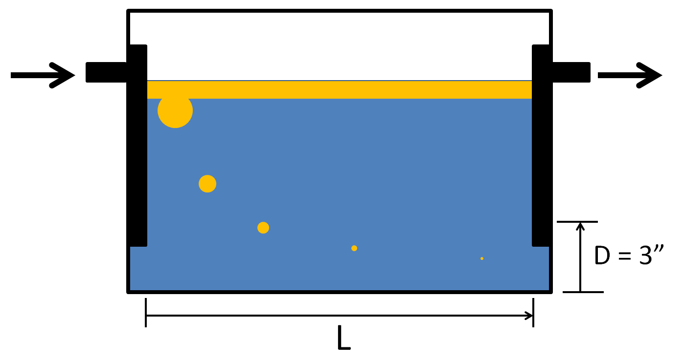
"For simplicity let us assume that pure grease and water enter near the bottom of a rectangular-shaped interceptor L feet long, B feet wide, and with a water depth of D feet.  The interceptor will do a good job of separation if, as the flow goes through the interceptor, the mean velocity of flow is such as to permit the grease globule to rise a vertical distance D in a length of L feet."

Dawson et al. went on to say, "If we neglect, for the moment, the presence of turbulence we see that the controlling item in the sizing of the interceptor for any particular rate of flow is the rate of rise of the grease globules. If the size of the globules is known, the maximum velocity of rise can be calculated readily from known principles of fluid mechanics, by equating the buoyant force on a globule to the force of fluid resistance."

If I keep quoting Dawson et al. we are all going to be asleep soon. So let me paraphrase from here. Velocity is the speed that the fluid is moving across the interceptor.  If the fluid moves too quickly the smaller grease globules are less likely to have time to rise an adequate distance to remain in the interceptor.  This makes velocity a key to good interceptor design.

The American Society of Plumbing Engineers (ASPE) established three inches as the minimum distance D that a grease globule must rise in a length of L in an interceptor to be retained (ASPE Plumbing Engineering Design Handbook 4, Plumbing Components and Equipment, Chapter 8 Grease Interceptors).

Gravity-differential separation applies to any grease interceptor regardless of manufacturer or type. HGIs must be designed based on this principle and so do GGIs.

No exceptions.

So what is the assumed difference?
That HGI's use controlled flow and some other stuff, most of which is bunk (counter-current flows, bernoulli's equation, etc.), to do what GGIs do with retention time.

Assumption debunked.

HGIs control the incoming flow and distribute it throughout the cross-sectional area reducing the fluid velocity to allow for gravity-differential separation at the maximum rated flow of the interceptor.

GGI's do not!

This is basic physics.

GGIs simply take whatever flow is dumped into them and everyone assumes that, no matter what, the GGI can handle it.

Sorry, it ain't possible.

Uncontrolled inlet velocity and the associated turbulence causes short-circuiting at higher flow rates in GGIs. This is not to say that GGIs don't work.  At lower flow rates they work very well because turbulence decay happens rapidly at low flow rates.  At higher flow rates though, turbulence decay happens over an exponentially longer time.

Experiments by the Water Environment Research Foundation, included in their 2008 report Assessment of Grease Interceptor Performance, demonstrated that residence times of at least one hour were more conducive to turbulence decay in the standard IAPMO approved GGI (Z1001) design.

When everyone finally steps back long enough to think clearly about how all grease interceptors must actually work - we will finally be able to start focusing on what is really important in an interceptor (hint - it isn't how much water it can hold).

When everyone starts focusing on how efficient a grease interceptor is and how much grease it can hold instead of how much water it can hold, we wont need to worry about whether its called an HGI or a GGI because all grease interceptors will be just grease interceptors.

HGIs will not hold just 2 lbs of grease for each 1 gpm of flow rate - because to keep up with competition, they will have to hold 5 times as much or 10 times as much or even more!

If GGIs are the FOG abatement solution of the future then the earth doesn't revolve around the sun and the moon doesn't revolve around the earth and we don't exist either, which is weird because my back hurts.

Wednesday, April 2, 2014

How do Gravity Grease Interceptors Work and How Efficient are they?

Many jurisdictions across the United States either favor exterior gravity interceptors or outright mandate them, some going as far as disallowing hydromechanical grease interceptors altogether.  

I get it.  I understand why.  Jurisdictions are frustrated!

For many decades grease traps (now called hydromechanical grease interceptors - HGI) have been the primary pretreatment device prescribed by plumbing codes to be installed in commercial food service establishments to prevent grease from entering the collection system.

If they work so well, why have jurisdictions been having so many issues with the buildup of FOG in collection systems?  

A simple inspection of the restaurants in a lot of jurisdictions will reveal a significant number of undersized indoor grease interceptors that are connected only to a multi-compartment sink and are not being maintained frequently enough.  

Hey, Americans are some of the best ditch divers (going from one extreme to another) in the world.  If the problem is allowing restaurants to install undersized grease interceptors inside the kitchen, then the "fix" is only allowing swimming pool sized gravity interceptors outside, right?!

How efficient are these giant interceptors?  How much grease will they hold?

I have asked jurisdictions across the country from sea to shining sea these same questions for the past 5 years, and you know what the answer always is?  "I don't know" - that's the answer. No one knows.  

How is it possible that we have jurisdictions mandating and in some cases only allowing the installation of interceptors whose efficiency and grease storage capacities are unknown?

I suppose the most common argument I hear is that basic physics justify their approval.  Okay, what physics are we talking about?  Stokes law.  The universally accepted answer as to why gravity interceptors work is because of Stokes law and retention time.

Really?  Okay, so what is Stokes law and how does it work?

Stokes law explained
The American Society of Plumbing Engineers (ASPE), Plumbing Engineering Design Handbook 4, Plumbing Components and Equipment, covers grease interceptors in chapter 8. Regarding Stokes law it has this to say on page 153: 


"An examination of this equation shows that the vertical velocity of a grease globule in water depends on the density and diameter of the globule, the density and viscosity of the water, and the temperature of the water and FOG material. Specifically, the grease globule's vertical velocity is highly dependent on the globule's diameter, with small globules rising much more slowly than larger ones. Thus, the larger the globule, the faster the rate of separation."


Table 8-1 Droplet Rise Time
Travel Time for 3" Distance at   68 deg F (hr:min:sec) Travel Time for 3" Distance at   68 deg F (hr:min:sec)
Droplet Diameter (microns) Oil (rise time) SG 0.85 Droplet Diameter (microns) Oil (rise time) SG 0.90
300 0:00:12 300 0:00:15
150 0:00:42 150 0:01:03
125 0:01:00 125 0:01:27
90 0:01:54 90 0:02:54
60 0:04:12 60 0:06:36
50 0:06:18 50 0:09:18
40 0:09:36 40 0:14:24
30 0:17:24 30 0:25:48
20 0:38:46 20 0:58:08
15 1:08:54 15 1:43:22
10 2:35:02 10 3:52:33
5 10:02:09 5 15:30:14
1 258:23:53 1 387:35:49

In the table above ASPE calculated the different rise rates of grease globules based on size in microns, and two different specific gravities (SG) - 0.85 and 0.90, showing how long it would take them to rise 3 inches at 68 deg. F.

Quoting ASPE again:

"Due to reliance on gravity differential phenomena, there is a practical limitation to interceptor effectiveness. In terms of grease/oil globule size, an interceptor will be effective over a globule diameter range having a lower limit of 0.015 centimeter (150 microns)."

Stokes law is fairly straight forward with one catch; it calculates the rate of rise of a grease globule in static (not moving) water. Does a grease interceptor, whether HGI or gravity, contain static water? Obviously not.  Either type of interceptor will have fixtures draining waste water into them at some flow rate.  How does this flow of waste water affect the calculation of Stokes law?

We need to understand the difference between laminar and turbulent flow before attempting to ascertain their affect on the calculation of Stokes law.

According to the Encyclopedia Britannica:
Turbulent Flow

  • Turbulent flow is fluid flow in which the fluid undergoes irregular fluctuations, or mixing. The speed of the fluid at a point is continuously undergoing changes in magnitude and direction, which results in swirling and eddying as the bulk of the fluid moves in a specific direction.
  • Laminar flow is fluid flow in which the fluid travels smoothly or in regular paths. The velocitypressure, and other flow properties at each point in the fluid remain constant. Laminar flow over a horizontal surface may be thought of as consisting of thin layers, all parallel to each other, that slide over each other. 
It is impossible to accurately predict the rise rate of a globule of grease in a turbulent flow environment because the turbulent flow acts to re-entrain the grease into the flow path negating the buoyant forces that are acting to lift the grease globule to the surface (depending on its size of course).

The advantage of a laminar flow environment is that the flow has very little effect (adding drag) on the buoyant forces acting on a grease globule.

Quoting again from page 155 of the same ASPE handbook:

"The ability of an interceptor to perform its primary function depends on a number of factors. These include the type and state of FOG in the waste flow, the characteristics of the carrier stream [turbulent vs. laminar], and the design and size of the unit."

Quoting from a paper published in 1944 titled Symposium on Grease Removal, Design and Operation of Grease Interceptors, by F.M. Dawson and A.A. Kalinske: 


"For simplicity let us assume that pure grease and water enter near the bottom of a rectangular-shaped interceptor L feet long, B feet wide, and with a water depth of D feet. The interceptor will do a good job of separation if, as the flow goes through the interceptor, the mean velocity of the flow is such as to permit a grease globule to rise a vertical distance D in a length of L feet."

Let's go back to our ASPE handbook:

"The ideal separation basin is one that has no turbulence, short-circuiting, or eddies.  The flow through the interceptor is laminar and distributed uniformly throughout the basin's cross-sectional area."

Distributing the flow uniformly throughout the basin's cross-sectional area reduces velocity which allows more time for a grease globule to separate inside the interceptor before reaching the outlet and escaping.  The velocity of the flow is reduced proportional to the extent to which it is uniformly distributed throughout the basin's cross-sectional area. 

The question is; do gravity interceptors have a laminar flow path and do they uniformly distribute the flow throughout their cross-sectional areas?
IAPMO/ANSI Z1001 Gravity Grease Interceptor

Here is what the standard gravity interceptor design looks like; the design that is mandated by IAPMO/ANSI Z1001 (formerly PS-80) and approved by model plumbing codes and most jurisdictions:

According to the Water Environment Research Foundations' 2008 report Assessment of Grease Interceptor Performance:  


Figure 5-18
"The standard configuration [IAPMO/ANSI Z1001] displayed substantially poorer performance than any of the other simulations (56.7%). Close observation of the velocity contours (Figure 5-18) of the cross-section within the reactor suggests that the cause for this reduced performance may be due to higher local velocities near the inlet, baffle, and outlet pipes, all contributing non-quiescent (turbulent) flow conditions...Further examination of the velocity contours in the direction of flow (Figure 5-19) suggests several regions of high velocity along the bottom of the tank and along the side walls."


WERF is essentially saying that at higher flow rates the lack of any control over the flow in gravity interceptors exacerbates turbulence and horizontal velocity leading to short-circuiting.


Figure 5-19
The simulations and bench tests pictured in Figure 5-18 and 5-19 represent a 20 minute retention time, which would be 50 gpm entering a 1000 gallon gravity interceptor. That is obviously a significant amount of flow and in fairness is higher than the average flow rate from most FSEs.


WERF's 2008 report also documented Grease Interceptor Influent Fluid Flow Analysis conducted on several different food service establishments (FSE) in Table 4-3 page 4-8.  The data collected included the total flow to the grease interceptor, the maximum flow-rate measured, the average flow-rate for the measurement period, and the size of the interceptor, among other things.


The outlier on maximum flow-rate across all restaurants was 45 GPM at a ‘full service steak house’. The average flow-rate at this same restaurant was 9.8 GPM.  The second highest flow-rate recorded was 35 GPM at a ‘full fare – Italian’ restaurant and the average flow-rate for this FSE was 9.4 GPM. The average flow rate for all restaurants was 2.8 gpm.

It is important to understand that the flow rates from these FSEs have low averages because restaurants don't typically fill up all their sinks and dump them repeatedly all day long.  Normal kitchen operations have some flow associated with both cooking and cleaning throughout the day, however, when they pull the drain plugs at the end of a meal period or the end of the day - this is when they will have a significant amount of flow at higher temperatures.

Based on all of the factors that effect grease interceptor performance, we would expect that a gravity grease interceptor would perform well at the average flow rates of most restaurants. However, we should also expect them to have problems with short circuiting at higher flow rates, and this is in fact what WERF reported finding in their analysis of interceptors in real world installations.  

Conclusion
On page 156 of the handbook we've been referring to here, ASPE explains:

"you can improve the grease interceptor by increasing the interceptor volume or reducing flow and subsequently lowering horizontal velocity and increasing retention time within the interceptor."

Therefore, gravity interceptors will actually need to be bigger in order to prevent short circuiting at higher flow rates - a decision that has consequences both positive and negative (i.e. better efficiencies but H2S gas generation).

Hydromechanical interceptors, though smaller in size and volume, have the advantage of being able to control the entering waste stream creating a laminar flow environment and distributing that flow more or less uniformly throughout their cross-sectional area, thereby reducing horizontal velocity and increasing flow through time.  This is why they are a viable alternative to larger gravity interceptors.

The challenge is to ensure that they are sized to have all of the kitchen fixtures routed to them, in order to avoid inadvertent bypass, and then to make sure they are maintained properly -(both subjects of another post).

Tuesday, March 25, 2014

Mandated Design Requirements for Grease Interceptors; Why its a Bad Idea!

Many jurisdictions mandate prescriptive design elements for grease interceptors like, “must have a minimum of two compartments” or “must have a minimum liquid holding capacity of 500/750/1000 gallons”, etc.

Many of the design elements that we find required by jurisdictions are based on the extrapolation of engineering principles such as Stokes law, but most have never been proven to enhance interceptor performance.  Any design for a grease interceptor should of course be based on fundamental engineering principles, but as you will see that is only the beginning of the process of design development.

Back to the beginning
Prior to the 1940’s grease interceptor manufacturer’s each rated their own interceptors and produced them in a variety of sizes and types according to engineer’s specifications or to satisfy plumbing codes.  There was no uniform testing or rating procedure for grease interceptors.

In 1944 the researchers from the Iowa Institute of Hydraulic Research (IIHR) attended the Sixteenth Annual Meeting of the New York State Sewage Works Association where they presented a symposium of four papers, one of which was titled Symposium on Grease Removal - Design and Operation of Grease Interceptors, by F. M. Dawson and A. A. Kalinske.

In this paper, the authors explain how the researchers from IIHR developed the testing and rating method for grease interceptors that the Plumbing and Drainage Manufacturer’s Association (now the Plumbing and Drainage Institute) would later formalize into the standard PDI-G101. 

Fundamentals of Operation
Fats, oils and grease (FOG) float in water owing to a difference in their specific gravity.  Water has a specific gravity of 1.0 while the specific gravity of olive oil is 0.703, lard is 0.875, and vegetable oil is 0.92 which is why they all float.  Interceptors are designed to separate FOG based on the differences in specific gravity which is called “gravity-differential separation”

Stokes law predicts the rise rate of a grease globule in static water based on its size, temperature, viscosity and specific gravity.  For example, in static water with a temperature of 150o F, a grease globule with a size of 150 microns and a specific gravity of 0.90 will have a rise rate of 0.05 feet per second. 

All other factors being the same, a grease globule of 50 microns will take 9 times longer to rise than a grease globule of 150 microns. For this reason researchers concluded that interceptors should be designed to separate grease globules of about 150 microns because, “the rate of rise of globules much less than this size is so small that gravitational separation is impracticable, and globules much larger than this will be easily separated.”

So we see from the beginning that researchers started with the fundamental engineering principles of Stokes law and the differing specific gravities of fats, oils, grease and water.  From this they calculated some basic ratios for an interceptor’s length, width and height and the internal velocity that should allow for the proper separation of FOG according to Stokes law and the differences in specific gravity.

Engineering is never as simple as that.  For example, Stokes law can predict the rise rate of a globule of grease in a static (non-moving) body of water, given that we know the size of the globule, its specific gravity, its temperature, and its viscosity.  If the water is moving do we know if the flow laminar or turbulent?  If it is laminar (turbulent free) the rise rate may still be predictable, but how do you calculate for turbulent flow?  What about velocity?  Velocity is a function of the entering flow rate and the cross sectional area the flow passes through as it moves across the interceptor.  How do we know if a design does a good job in spreading out the entering flow sufficiently to mitigate the velocity and allow for gravity differential separation?

Because no amount of work with a calculator can answer these questions, designs must be tested, their performance evaluated and adjustments made to improve the design until it achieves the desired performance. 

This is why jurisdictions should not mandate specific prescriptive design elements for grease interceptors. How do we know that the mandated design elements work in an interceptor?   

Let’s consider a couple specific design elements typically mandated
Must have a minimum of two compartments – What is the basis for this requirement?  There are many claims of enhanced performance but where are the scientific studies that prove the benefit?  On the contrary studies such as the Assessment of Grease Interceptor Performance by the Water Environment Research Foundation (WERF) published in 2008 raise serious concerns over the inclusion of a baffle wall (creating two compartments) in traditional gravity interceptor designs citing, among other things, short circuiting (unexpected bypass).

Must have a minimum liquid holding capacity of 500/750/1000 gallons – What does the amount of water an interceptor can hold have to do with how efficient the interceptor is?  The answer is nothing directly.  How much grease will a 500/750/1000 gallon gravity interceptor efficiently hold?  The answer is that no one knows. Traditional gravity interceptors that comply with these minimum liquid capacities have an Achilles heal; they are not tested and rated for performance.  The answers to any questions regarding the performance of these interceptors can only be guessed because there is no scientific data that proves that a minimum amount of liquid holding capacity will provide assurance of performance.

A better way
Instead of telling us what you want an interceptor to look like, why not tell us what you want it to actually do?  For instance:
  • How efficient should an interceptor be?  Should it be required to be tested to prove that it meets the requirement?
  • How much grease should an interceptor be required to separate and store?  Should it be required to be tested to prove that it meets the required storage capacity?

If jurisdictions would get out of the design business and instead focus on approving performance standards for interceptors this would create an environment that would encourage innovation in designs with a focus on better efficiency and storage capacities. 

That’s how jurisdictions will get what they really want out of an interceptor!

Tuesday, March 18, 2014

Why Effluent Concentration Limits for Grease Interceptors is not Appropriate

Proper grease interceptor maintenance is a critical component to any FOG abatement program.  The challenge for jurisdictions is figuring out when an interceptor is full and how often it should be maintained.

One of the solutions that many jurisdictions have adopted is to set a numeric concentration limit for the effluent of an interceptor such as 100 ppm (parts per million) or 100 mg/L (milligrams per liter).  An inspector will take a grab sample from the effluent of an interceptor and measure the amount of FOG in the sample using EPA method 1664A to determine if the interceptor is in compliance or whether an enforcement action is required to get the interceptor back into compliance.

There are two problems with this approach, lets address them both.

The first problem with using effluent concentration limits for determining grease interceptor compliance issues is that grease interceptors are not designed to meet a specific effluent concentration limit and never have been. When you understand how grease interceptors are designed to work you'll understand why it would be inappropriate to use an effluent concentration limit to determine interceptor compliance issues.

Up until the early 1940’s there was chaos in the interceptor world because each manufacturer rated their own interceptors and produced them in a variety of sizes and types according to engineer’s specifications or to satisfy plumbing codes.  There was no uniform testing or rating procedure for grease interceptors.

In 1946 the Iowa Institute of Hydraulic Research (IIHR) published a bulletin on its activities and had this to say regarding grease interceptors, “The institute has for many years been engaged in research and testing relating to grease interceptors…and has been instrumental in developing testing standards and methods of rating for such interceptors.  During the war large numbers of grease interceptors were required in the kitchens of army cantonments and similar establishments.  With the cooperation of the construction branch of the Army Engineers and the interceptor manufacturers, a standard test method was developed.” (1)

Prior to the publication of the aforementioned bulletin, in 1944 the researchers from the IIHR attended the Sixteenth Annual Meeting of the New York State Sewage Works Association where they presented a symposium of four papers, one of which was titled Symposium on Grease Removal - Design and Operation of Grease Interceptors, by F. M. Dawson and A. A. Kalinske.(2)

In this paper, the authors explain how the researchers from IIHR developed the testing and rating method that the Plumbing and Drainage Manufacturer’s Association (now Plumbing and Drainage Institute) would later formalize into the standard PDI-G101. 

The performance requirements that came from this testing and were later formalized in PDI-G101 (and later in ASME A112.14.3 and CSA B481) mandated that an interceptor must have an average efficiency of 90% and be capable of storing at least 2 lbs of grease for each 1 gpm of flow rate.  

Fundamentals of operation
Fats, oils and grease (FOG) float in water owing to a difference in their specific gravity.  Water has a specific gravity of 1.0 while the specific gravity of olive oil is 0.703, lard is 0.875, and vegetable oil is 0.92 which is why they all float.  Interceptors are designed to separate FOG based on the differences in specific gravity which is called “gravity-differential separation”(2). 

Stokes law predicts the rise rate of a grease globule in static water based on its size, temperature, viscosity and specific gravity. For example, in static water with a temperature of 150 deg F, a grease globule with a size of 150 microns and a specific gravity of 0.90 will have a rise rate of 0.05 feet per second.

All other factors being the same, a grease globule of 50 microns will take 9 times longer to rise than a grease globule of 150 microns. For this reason researchers concluded that interceptors should be designed to separate grease globules of about 150 microns because, “the rate of rise of globules much less than this size is so small that gravitational separation is impracticable, and globules much larger than this will be easily separated.”(2)

The size of the grease globules entering an interceptor is a result of the level of emulsification between the grease and water.  

Emulsification is the mixing of immiscible liquids (liquids that don't naturally mix), which can be caused mechanically or chemically.  

Mechanical emulsification occurs by washing dishes by hand in a sink and then pulling the drain plug or in a dishwasher by means of spray jets and drainage action.  

Chemical emulsification occurs when soap or detergents are used.  Soaps are surfactants and detergents contain surfactants which act to chemically bond with oil droplets making it easier for them to be separated from each other and more difficult for them to coalesce together again.  

A grease interceptor has no control over the level of emulsification of the entering grease and waste water and are not designed to cause grease to coalesce inside the unit, although in a laminar flow environment some coalescence will naturally occur.

A grease interceptor is designed to separate grease from waste water that is a minimum of 150 microns in size with an average efficiency of 90% and have a storage capacity of at least 2 lbs of grease for each 1 gpm of its certified flow rate.

150 microns = .15 mm
50 microns = .05 mm

The smallest object the human eye can detect is around .04 mm.  What this means is that if you observe the effluent from an interceptor you could potentially see very small grease globules escaping even though the interceptor is being properly maintained is in functioning correctly. 

If a grab sample taken from the effluent from an interceptor contains a significant amount of very small grease globules (anything less than 150 microns) the sample could produce results that indicate an effluent concentration of greater than 100 mg/L even though the interceptor is operating properly.  

The second problem with using effluent concentration limits for determining grease interceptor compliance issues is that EPA test method 1664A is flawed yielding a high degree of variability in test results.

In 2008 the Water Environment Research Foundation (WERF) released a comprehensive study of grease interceptor's in real world installations titled Assessment of Grease Interceptor Performance. Regarding the use of EPA test method 1664A WERF stated, “as an indirect outcome of this study, the FOG concentration measurement results showed that the EPA Method 1664 displayed significant variability when measuring known concentrations of total oil and grease. Variability in the measured concentration was approximately 40%, making it impossible to confirm or refute whether the grease interceptor is properly achieving the required effluent limit.”(3)  

Summary
Grease interceptors are designed to separate grease based on a minimum size of 150 microns.  Anything smaller is expected to bypass the grease interceptor because to design an interceptor to separate out smaller grease globules would require the unit to be dramatically larger and impracticable to install and maintain.  

Using effluent concentration limits to determine grease interceptor compliance could and likely will yield results that may be outside of set jurisdictional limits but may have been the result of highly emulsified grease and waste water containing a significant amount of grease that was less than 150 microns in size escaping the interceptor.  

Finally, EPA test method 1664A is flawed, potentially yielding test results with as much as a 40% error rate, according to WERF.

Instead of using numeric concentration limits for compliance enforcement on grease interceptors, jurisdictions should instead concentrate on allowing only grease interceptors that are certified with known efficiencies and storage capacities and require them to be maintained regularly and properly.  

How often they should be cleaned is a function of how much grease a restaurant produces and how much grease storage capacity the interceptor has.  Here is where I will plug Schiers grease production sizing method (check out the 2014 catalog at www.schierproducts.com), because it helps a jurisdiction and an owner be able to figure out how much grease is being produced so a proper maintenance schedule can be established.


References
(1) The University of Iowa Studies in Engineering, page 60, The Iowa Institute of Hydraulic Research, 1946, http://ir.uiowa.edu/uisie/30
(2) Symposium on Grease Removal, Design and Operation of Grease Interceptors, Water Environment Federation, Sewage Works Journal, Vol. 16, No. 3, F.M. Dawson and A. A. Kalinske, Iowa Institute of Hydraulic Research, 1944, http://www.jstor.org/stable/25029790
(3) Assessment of Grease Interceptor Performance, page 116, Water Environment Research Foundation, 2008, http://www.ndwrcdp.org/documents/03-cts-16t/03cts16taweb.pdf

Tuesday, March 4, 2014

Kitchen fixtures and grease interceptors; does it matter?

Some plumbing codes have exacerbated FOG related pretreatment problems by incorporating vague language regarding which fixtures should be routed through an interceptor.  Extensive field inspections have proven that FOG is being introduced through every fixture in the kitchen at one point or another.

For some reason not everyone thinks that floor drains or floor sinks need to be routed to an interceptor.  Yet spills like the one pictured here are very common.  We would advise that the kitchen staff isolate a spill like this and use absorbent materials to clean it up carefully.  Yet when it gets busy its more likely that someone with a mop and bucket will rush to the area and "do their best" to get it mopped up or at least liquid enough to squeegee into a nearby floor drain or floor sink.  


We know that dish ware that ends up in a multi-compartment sink is going to produce a significant amount of FOG, but fixtures such as bar sinks get over looked. Yet some common sources of FOG are cappuccino, cafe' breva, cafe' macchiato, cafe' latte, cafe' mocha, frappuccino, hot chocolate, iced cafe's with milk or cream, milk shakes, mixed alcoholic beverages with milk or cream such as white russian, irish coffee, kahlua and cream and so on.  The point being that milk fat is very common and found in many bar drinks where associated glass ware is typically also rinsed and washed.

The best way to prevent a restaurant from discharging FOG to the collection system is to connect all of the following fixtures to a properly sized, installed and maintained grease interceptor:
  • sinks used for washing pots, pans, dishes, cutlery, kitchen utensils, including pre-rinse sinks
  • drains serving self-cleaning exhaust hoods installed over commercial cooking equipment
  • drains serving commercial cooking equipment that discharges oil and grease (i.e. woks, soup kettles, tilt kettles, etc.)
  • drains serving garbage compactors used to compact waste that may contain, or be contaminated with food waste
  • floor drains
  • floor sinks
  • mop sinks
There are two remaining fixtures which should be carefully considered:
  • Dishwasher discharge is a high-temperature mixture of FOG, solids, water and surfactants from excess detergent.  Testing has shown that higher temperatures actually assist in separation performance.  However, interceptors are designed to separate free floating FOG not FOG that has been emulsified by surfactants.  Some jurisdictions believe that it is better to route the dishwasher through the grease interceptor and hope that excess surfactants do not emulsify previously captured FOG, rather than guarantee that the FOG and solids in the dishwasher effluent are delivered directly to the collection system by not routing it through the grease interceptor.
  • Many FSEs scrape dirty dishes into their food waste disposal unit increasing FOG-laden solids that can be discharged to the collection system.  This is a good reason to route these fixtures to a grease interceptor.  However, extra solids loading from a food waste disposal unit can be problematic. To help prevent the interceptor from prematurely filling up with food waste, jurisdictions can require a solids interceptor after a food waste disposal unit or, ultimately, consider eliminating food waste disposal units altogether to improve interceptor performance and reduce the amount of total suspended solids (TSS) entering the collection system.